development / project / fwdarch /
Refurbishing the FORWARD module
The purpose of this page is just to serve as todo or scratch pad for the development project and to list and share some ideas.
After making changes to the code and/or documentation, this page should remain on the website as a reminder of what was done and how it was done. However, there is no guarantee that this page is updated in the end to reflect the final state of the project
So chances are that this page is considerably outdated and irrelevant. The notes here might not reflect the current state of the code, and you should not use this as serious documentation.
The forward module routines generate leadfields which are used used in different contexts (e.g., beamformer). To build the forward model we make use of various methods and we start from very different geometrical descriptions, generally representing the head shape.
Let’s list some of the methods currently supported by FieldTrip (in parentheses which modality they are used for):
- ASA bem (EEG)
- Bemcp (EEG)
- Dipoli bem (EEG)
- OpenMEEG bem (EEG/MEG)
- MNE bem (do we want to adopt this?)
- halfspace medium (EEG)
- Infinite medium (EEG/MEG)
- Infinite slab (EEG)
- Local spheres (EEG/MEG)
- Single shell (MEG)
- Concentric spheres (EEG)
According to the different anatomy acquisition techniques it is possible to distinguish among the following types of input:
- CT scan
- MRI scan
- Headshape, points
- Headshape, closed surface
- Nothing
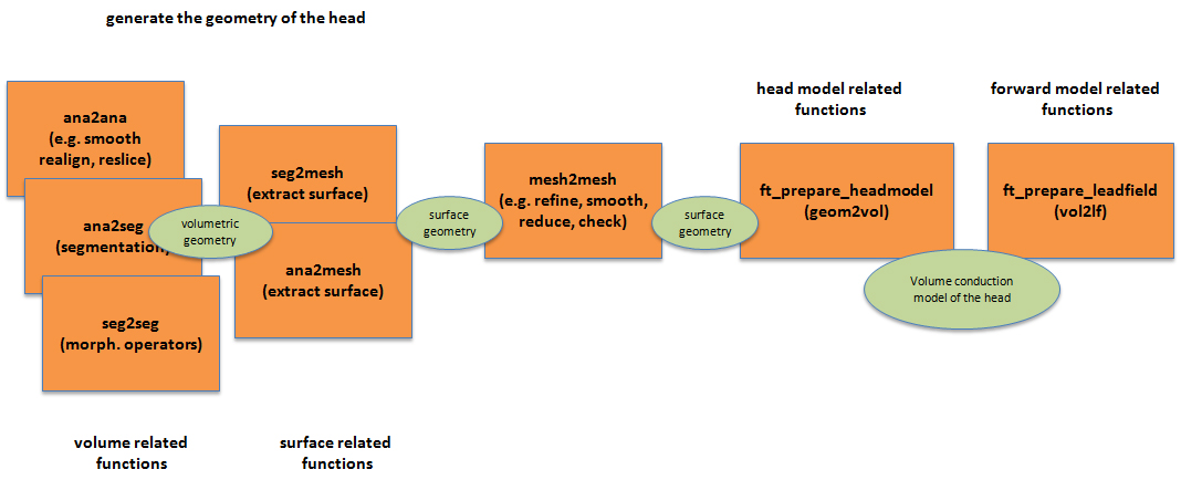
All the routines which create a forward model need a description of the volume conductor model as input. This model is represented in a vol structure which contains a set of fields, among which vol.method (e.g., vol.method = ‘dipoli’). All other fields are specific for the various methods and are generated in a pipeline which can be summarized in the following picture
)
The leftmost box indicates a set of functions (MATLAB/external toolboxes, FieldTrip) that deal with anatomical volumes (a 3D matrix filled with intensity values - a set of voxels). This step manages the volumetric information (MRI/CT scans) and transforms the anatomy into a processed anatomy (‘ana2ana’ functions), transforms the anatomy into a binary segmentation (‘ana2seg’ functions) or manipulates segmented images (‘seg2seg’ functions, i.e. morphology operators).
The content of the central box is a set of functions which refines the geometrical description derived from the volumetric analysis. Any visual quality control is processed in this section, including interactions with the operator. The input can be a segmented volume, a triangulated set of points or a cloud of points. The output is a geometry (geom), defined as a geometrical description other than volumetric, like for example a triangulated mesh, a cloud of points representing the head, a 3D lattice of tetrahedra/hexahedra, etc.
The third block (Post-processing) performs all automatic steps to build the description of the volume conductor (‘vol’ structure with various fields). This last step provides the piece of information which is fed to the forward solution algorithms (the various lead field computation routines). This post-processing functions are not supposed to change the meshes anymore and call method-specific head model functions (ft_headmodel_XXX routines)
As a general rule all volumetric geometry descriptions should not contain holes or be hollow. All mesh geometries (excluded 3D meshes for FEM) should not intersect with each other or be nested (apart for concentric spheres).
Architecture: defining a table for the possible implementations
The table contains the cells that indicate FROM which kind of input TO which kind of method I want to go. The content is a set of programmatic steps which leads from a specific anatomical information (see the first column) to the costruction of the ‘vol’ structure for a forward model method (see the first row of the table).
The tables are different for EEG and MEG:
For EEG
| ^ Infinite ^ Halfspace ^ Slab ^ Single sphere ^ Concentric spheres ^ FEM ^ FDM ^ ASA BEM ^ Bemcp ^ Dipoli BEM ^ OpenMEEG BEM ^ | |||||||||||
|---|---|---|---|---|---|---|---|---|---|---|---|
| 1.CT | INF | HS1 | SL1 | SPH1 | CS1 | FEM1 | FDM1 | ASA | BEMCP1 | DIP1 | OM1 |
| 2.MRI | INF | HS2 | SL2 | SPH2 | CS2 | FEM2 | FDM2 | ASA | BEMCP2 | DIP2 | OM2 |
| 3.Headshape points | INF | HS3 | SL3 | SPH3 | CS3 | n.a. | n.a. | ASA | BEMCP3 | DIP3 | OM3 |
| 4.Headshape triangulation | INF | HS4 | SL4 | SPH4 | CS4 | n.a. | n.a. | ASA | BEMCP4 | DIP4 | OM4 |
| 5.Nothing | INF | HS5 | SL5 | SPH5 | n.a. | n.a. | n.a. | n.a. | n.a. | n.a. | n.a. |
For MEG
| ^ Infinite ^ Single sphere ^ Local spheres ^ Single shell ^ FEM ^ OpenMEEG BEM ^ | ||||||
|---|---|---|---|---|---|---|
| 1.CT | INF | SPH1 | LS1 | SH1 | FEM1 | OM1 |
| 2.MRI | INF | SPH2 | LS2 | SH2 | FEM2 | OM2 |
| 3.Headshape points | INF | SPH3 | LS3 | SH3 | n.a. | OM3 |
| 4.Headshape triangulation | INF | SPH4 | LS4 | SH4 | n.a. | OM4 |
| 5.Nothing | INF | SPH5 | n.a. | n.a. | n.a. | n.a. |
Overview on the methods
The following paragraphs describe in synthesis the pipelines for the various methods sketched in the tables. The methods are ordered according to the input type (e.g., CT scans) they use to generate the ‘vol’ structure.
Having a CT scan and EEG data
INF1 method
From CT to Infinite space
In case the anatomy description is available, it is not used to generate the infinite-medium forward solution. A structure that describes an infinite-medium volume conduction model is generated with only one field: headmodel.type = 'infinite'.
HS1 method
FROM CT TO Infinite halfspace
This applies for example when the set of electrodes is distributed on a flat surface (e.g., Utah array) Method:
- Assign a transformation matrix (voxels to mm/cm) and units to the volumetric images. This step is necessary to link the units in which the head sources are defined (for example expressed in cm and head coordinates) to the voxel based coordinate system.
- Reslice the CT volume in order to obtain homogeneous voxels (cubic). The reslice step accomplishes the task of having 3 equal edges (in the cartesian or voxel coordinates) for each voxel. This allows the application of morphological operators, which give a predictable outcome only in the case of cubic voxels.
- Segment the skull compartment (smooth/threshold volumetric operators). The skull compartment defines the boundary of the volume conductor (inner skull) and the scalp boundary (outer skull). This geometrical information is used by the forward model.
-
Obtain the filled volume of the inner skull (morphological operators). The volumetric compartments can be easily tessellated (see HERE) if the volume is filled.
- With the diverse triangulation techniques obtain the points of the triangulated surface around the inner skull volume
- Calculate a plane tangent to the inner skull points
- Determine one point on the non-conductive side of the electrodes
- [only for the Slab method] Determine the thickness of the slab (e.g., cortical thickness)
- Electrodes are not allowed to be in the vacuum side, therefore faulty electrodes are automatically reprojected on the plane
SL1 method
FROM CT TO Infinite slab
This applies for example when the set of electrodes is distributed on a flat surface (e.g., Utah array)
- Assign a transformation matrix (voxels to mm/cm) and units to the volumetric images. This step is necessary to link the units in which the head sources are defined (for example expressed in cm and head coordinates) to the voxel based coordinate system.
- Reslice the CT volume in order to obtain homogeneous voxels (cubic). The reslice step accomplishes the task of having 3 equal edges (in the cartesian or voxel coordinates) for each voxel. This allows the application of morphological operators, which give a predictable outcome only in the case of cubic voxels.
- Segment the skull compartment (smooth/threshold volumetric operators). The skull compartment defines the boundary of the volume conductor (inner skull) and the scalp boundary (outer skull). This geometrical information is used by the forward model.
-
Obtain the filled volume of the inner skull (morphological operators). The volumetric compartments can be easily tessellated (see HERE) if the volume is filled.
- With the diverse triangulation techniques obtain the points of the triangulated surface around the inner skull volume
- Calculate a plane tangent to the inner skull points
- Determine one point on the non-conductive side of the electrodes
- [only for the Slab method] Determine the thickness of the slab (e.g., cortical thickness)
- Electrodes are not allowed to be in the vacuum side, therefore faulty electrodes are automatically reprojected on the plane
SPH1 method
FROM CT TO Single sphere
This method applies to ECoG or sEEG and is normally not used for scalp EEG:
- Assign a transformation matrix (voxels to mm/cm) and units to the volumetric images. This step is necessary to link the units in which the head sources are defined (for example expressed in cm and head coordinates) to the voxel based coordinate system.
- Reslice the CT volume in order to obtain homogeneous voxels (cubic). The reslice step accomplishes the task of having 3 equal edges (in the cartesian or voxel coordinates) for each voxel. This allows the application of morphological operators, which give a predictable outcome only in the case of cubic voxels.
- Segment the skull compartment (smooth/threshold volumetric operators). The skull compartment defines the boundary of the volume conductor (inner skull) and the scalp boundary (outer skull). This geometrical information is used by the forward model.
-
Obtain the filled volume of the inner skull (morphological operators). The volumetric compartments can be easily tessellated (see HERE) if the volume is filled.
- Use one of the available triangulation methods to obtain the surface points of the volumetric compartments
- Fit a sphere to the points
- Fit a sphere on the volumetric image directly
CS1 method
FROM CT TO Concentric spheres
For a 3-sphere model the spheres represent the skin surface, the outside of the skull and the inside of the skull. For a 4-sphere model, the surfaces describe the skin, the outside-skull, the inside-skull and the inside of the cerebro-spinal fluid (CSF) boundaries.
Accordingly:
For 3 spheres:
- Assign a transformation matrix (voxels to mm/cm) and units to the volumetric images. This step is necessary to link the units in which the head sources are defined (for example expressed in cm and head coordinates) to the voxel based coordinate system.
- Reslice the CT volume in order to obtain homogeneous voxels (cubic). The reslice step accomplishes the task of having 3 equal edges (in the cartesian or voxel coordinates) for each voxel. This allows the application of morphological operators, which give a predictable outcome only in the case of cubic voxels.
- Segment the skull compartment (smooth/threshold volumetric operators). The skull compartment defines the boundary of the volume conductor (inner skull) and the scalp boundary (outer skull). This geometrical information is used by the forward model.
- Obtain the filled volume of the inner skull (morphological operators). The volumetric compartments can be easily tessellated (see HERE) if the volume is filled.
5 - Extract the filled volume of the outer skull using morphological operators 6 - Dilate the outer skull to estimate the scalp compartment 7 - For each compartment fit a sphere (see SPH1 method) 8 - Assign the conductivity to each compartment (from literature)
For 4 spheres: 7 - Erode the inner skull to estimate the inside of the CSF compartment 8 - For each compartment fit a sphere (see SPH1 method) 9 - Assign the conductivity to each compartment (from literature)
FEM1 method
FROM CT TO FEM
For a FEM model we have to represent as many different volumetric compartments as wanted. In the case of a CT scan we can identify the following tissue compartments: volume of the scalp, the skull, inside of the skull, inside of the CSF
- Assign a transformation matrix (voxels to mm/cm) and units to the volumetric images. This step is necessary to link the units in which the head sources are defined (for example expressed in cm and head coordinates) to the voxel based coordinate system.
- Reslice the CT volume in order to obtain homogeneous voxels (cubic). The reslice step accomplishes the task of having 3 equal edges (in the cartesian or voxel coordinates) for each voxel. This allows the application of morphological operators, which give a predictable outcome only in the case of cubic voxels.
- Segment the skull compartment (smooth/threshold volumetric operators). The skull compartment defines the boundary of the volume conductor (inner skull) and the scalp boundary (outer skull). This geometrical information is used by the forward model.
- Obtain the filled volume of the inner skull (morphological operators). The volumetric compartments can be easily tessellated (see HERE) if the volume is filled.
5 - Dilate the outer skull to estimate the scalp compartment 6 - Erode the skull to obtain the inner CSF compartment 7 - Check that each compartment does not contain holes, and fill them 8a - Use one of the triangulation methods to obtain th
-
- scalp surface
-
- scalp-skull interface
-
- skull-CSF interface
9a - Check the triangulations for intersections 10a - Using Tetgen to generate a set of tetrahedrons for: –the inner CSF compartment –the inner skull compartment –the skull –the scalp OR 8-10b - Generate a set of hexahedra using vgrid 11 - Assign the conductivity tensor to each -hedron element (from literature and DTI data) 12 - Check the consistency of tetrahedral/hexahedral normals (vertices order has to be consistent)
FDM1 method
FROM CT TO FDM
This method is based on anatomical description obtained from the segmentation of the CT scan. Normally the ‘elements’ of the FDM (Finite Differences Method) are the voxels of each compartment (as for example for the FNS method). Consequently it is important to obtain the segmentation of as many compartments as possible from the CT scan. Typically we will try to obtain: the scalp, the skull, the inner skull, the inner CSF compartments
- Assign a transformation matrix (voxels to mm/cm) and units to the volumetric images. This step is necessary to link the units in which the head sources are defined (for example expressed in cm and head coordinates) to the voxel based coordinate system.
- Reslice the CT volume in order to obtain homogeneous voxels (cubic). The reslice step accomplishes the task of having 3 equal edges (in the cartesian or voxel coordinates) for each voxel. This allows the application of morphological operators, which give a predictable outcome only in the case of cubic voxels.
- Segment the skull compartment (smooth/threshold volumetric operators). The skull compartment defines the boundary of the volume conductor (inner skull) and the scalp boundary (outer skull). This geometrical information is used by the forward model.
- Obtain the filled volume of the inner skull (morphological operators). The volumetric compartments can be easily tessellated (see HERE) if the volume is filled.
5 - Dilate the skull to estimate the scalp compartment 6 - Erode the skull to obtain the inner CSF compartment 7 - Assign the conductivity value to each compartment (from literature) 8 - Define the points in which the solution has to be calculated as:
- Deep brain points, OR
- The vertices of a previously defined surface (i.e. the scalp)
ASA1 method
FROM CT TO ASA BEM This method reads directly a ‘vol’ structure which is loaded from an external ‘ASA’ format file. Both the geometrical description of the head model and the system matrix are managed by the ANT software, from which the ASA format comes from.
BEMCP1 method
FROM CT TO BEMCP
This method generates a ‘vol’ structure which contains the conductivities of each compartment, the description of the triangulated surfaces and the system matrix (also called Head matrix), which accounts for the geometry of the head shape in the calculation of the lead fields.
- Assign a transformation matrix (voxels to mm/cm) and units to the volumetric images. This step is necessary to link the units in which the head sources are defined (for example expressed in cm and head coordinates) to the voxel based coordinate system.
- Reslice the CT volume in order to obtain homogeneous voxels (cubic). The reslice step accomplishes the task of having 3 equal edges (in the cartesian or voxel coordinates) for each voxel. This allows the application of morphological operators, which give a predictable outcome only in the case of cubic voxels.
- Segment the skull compartment (smooth/threshold volumetric operators). The skull compartment defines the boundary of the volume conductor (inner skull) and the scalp boundary (outer skull). This geometrical information is used by the forward model.
-
Obtain the filled volume of the inner skull (morphological operators). The volumetric compartments can be easily tessellated (see HERE) if the volume is filled.
- Extract the filled volume of the outer skull using morphological operators
- Dilate the outer skull to estimate the scalp compartment
- Erode the inner skull to estimate the inside of the CSF compartment
- Fill all the compartments with a flood fill algorithm
- Create a boundary for all the filled volumes with one of these methods
- [only for BEMCP] Create an additional 4th point for each triangle in each triangulated mesh (‘solid angle’ BEM method)
- Assign the conductivity to each compartment (from literature)
- Projection of the electrodes on the triangulated surface/s
- Check of the direction of the normals (outwards or inwards)
Dipoli1 method
FROM CT TO Dipoli
This method generates a ‘vol’ structure which contains the conductivities of each compartment, the description of the triangulated surfaces and the system matrix (also called Head matrix), which accounts for the geometry of the head shape in the calculation of the lead fields.
- Assign a transformation matrix (voxels to mm/cm) and units to the volumetric images. This step is necessary to link the units in which the head sources are defined (for example expressed in cm and head coordinates) to the voxel based coordinate system.
- Reslice the CT volume in order to obtain homogeneous voxels (cubic). The reslice step accomplishes the task of having 3 equal edges (in the cartesian or voxel coordinates) for each voxel. This allows the application of morphological operators, which give a predictable outcome only in the case of cubic voxels.
- Segment the skull compartment (smooth/threshold volumetric operators). The skull compartment defines the boundary of the volume conductor (inner skull) and the scalp boundary (outer skull). This geometrical information is used by the forward model.
-
Obtain the filled volume of the inner skull (morphological operators). The volumetric compartments can be easily tessellated (see HERE) if the volume is filled.
- Extract the filled volume of the outer skull using morphological operators
- Dilate the outer skull to estimate the scalp compartment
- Erode the inner skull to estimate the inside of the CSF compartment
- Fill all the compartments with a flood fill algorithm
- Create a boundary for all the filled volumes with one of these methods
- [only for BEMCP] Create an additional 4th point for each triangle in each triangulated mesh (‘solid angle’ BEM method)
- Assign the conductivity to each compartment (from literature)
- Projection of the electrodes on the triangulated surface/s
- Check of the direction of the normals (outwards or inwards)
OpenMEEG1 method
FROM CT TO OpenMEEG
This method generates a ‘vol’ structure which contains the conductivities of each compartment, the description of the triangulated surfaces and the system matrix (also called Head matrix), which accounts for the geometry of the head shape in the calculation of the lead fields.
- Assign a transformation matrix (voxels to mm/cm) and units to the volumetric images. This step is necessary to link the units in which the head sources are defined (for example expressed in cm and head coordinates) to the voxel based coordinate system.
- Reslice the CT volume in order to obtain homogeneous voxels (cubic). The reslice step accomplishes the task of having 3 equal edges (in the cartesian or voxel coordinates) for each voxel. This allows the application of morphological operators, which give a predictable outcome only in the case of cubic voxels.
- Segment the skull compartment (smooth/threshold volumetric operators). The skull compartment defines the boundary of the volume conductor (inner skull) and the scalp boundary (outer skull). This geometrical information is used by the forward model.
-
Obtain the filled volume of the inner skull (morphological operators). The volumetric compartments can be easily tessellated (see HERE) if the volume is filled.
- Extract the filled volume of the outer skull using morphological operators
- Dilate the outer skull to estimate the scalp compartment
- Erode the inner skull to estimate the inside of the CSF compartment
- Fill all the compartments with a flood fill algorithm
- Create a boundary for all the filled volumes with one of these methods
- [only for BEMCP] Create an additional 4th point for each triangle in each triangulated mesh (‘solid angle’ BEM method)
- Assign the conductivity to each compartment (from literature)
- Projection of the electrodes on the triangulated surface/s
- Check of the direction of the normals (outwards or inwards)
Having a MRI scan and EEG data
INF2 method
From MRI to Infinite space
In case the anatomy description is available, it is not used to generate the infinite-medium forward solution. A structure that describes an infinite-medium volume conduction model is generated with only one field: headmodel.type = 'infinite'.
HS2 method
FROM MRI TO Infinite halfspace
This applies for example when the set of electrodes is distributed on a very flat surface (e.g., Utah array) Method:
- Reslice the MRI volume in order to obtain homogeneous voxels (cubic)
- Segment the scalp with smooth/threshold operations
- Segment the brain compartments with SPM/FreeSurfer
- With fwdarch:#Morphology operators obtain the filled volumes
-
Obtain the brain compartment as brain = grey+white+csf and then apply smooth/threshold operators
- With the diverse triangulation techniques obtain the points of the triangulated surface around the inner skull volume
- Calculate a plane tangent to the inner skull points
- Determine one point on the non-conductive side of the electrodes
- [only for the Slab method] Determine the thickness of the slab (e.g., cortical thickness)
- Electrodes are not allowed to be in the vacuum side, therefore faulty electrodes are automatically reprojected on the plane
SL2 method
FROM MRI TO Infinite slab
This applies for example when the set of electrodes is distributed on a flat surface (e.g., Utah array)
- Reslice the MRI volume in order to obtain homogeneous voxels (cubic)
- Segment the scalp with smooth/threshold operations
- Segment the brain compartments with SPM/FreeSurfer
- With fwdarch:#Morphology operators obtain the filled volumes
-
Obtain the brain compartment as brain = grey+white+csf and then apply smooth/threshold operators
- With the diverse triangulation techniques obtain the points of the triangulated surface around the inner skull volume
- Calculate a plane tangent to the inner skull points
- Determine one point on the non-conductive side of the electrodes
- [only for the Slab method] Determine the thickness of the slab (e.g., cortical thickness)
- Electrodes are not allowed to be in the vacuum side, therefore faulty electrodes are automatically reprojected on the plane
SPH2 method
FROM MRI TO Single sphere
This method applies to ECoG or sEEG and is normally not used for scalp EEG:
- Reslice the MRI volume in order to obtain homogeneous voxels (cubic)
- Segment the scalp with smooth/threshold operations
- Segment the brain compartments with SPM/FreeSurfer
- With fwdarch:#Morphology operators obtain the filled volumes
-
Obtain the brain compartment as brain = grey+white+csf and then apply smooth/threshold operators
- Use one of the available triangulation methods to obtain the surface points of the volumetric compartments
- Fit a sphere to the points
- Fit a sphere on the volumetric image directly
CS2 method
FROM MRI TO Concentric spheres
FEM2 method
FROM MRI TO FEM
FDM2 method
FROM MRI TO FDM
ASA2 method
FROM MRI TO ASA BEM
This method reads directly a ‘vol’ structure which is loaded from an external ‘ASA’ format file. Both the geometrical description of the head model and the system matrix are managed by the ANT software, from which the ASA format comes from.
BEMCP2 method
FROM MRI TO BEMCP
This method generates a ‘vol’ structure which contains the conductivities of each compartment, the description of the triangulated surfaces and the system matrix (also called Head matrix), which accounts for the geometry of the head shape in the calculation of the lead fields.
- Reslice the MRI volume in order to obtain homogeneous voxels (cubic)
- Segment the scalp with smooth/threshold operations
- Segment the brain compartments with SPM/FreeSurfer
- With fwdarch:#Morphology operators obtain the filled volumes
-
Obtain the brain compartment as brain = grey+white+csf and then apply smooth/threshold operators
- Create a boundary for all the filled volumes with one of these methods
- [only for BEMCP] Create an additional 4th point for each triangle in each triangulated mesh (‘solid angle’ BEM method)
- Assign the conductivity to each compartment (from literature)
- Projection of the electrodes on the triangulated surface/s
- Check of the direction of the normals (outwards or inwards)
Dipoli2 method
FROM MRI TO Dipoli
This method generates a ‘vol’ structure which contains the conductivities of each compartment, the description of the triangulated surfaces and the system matrix (also called Head matrix), which accounts for the geometry of the head shape in the calculation of the lead fields.
- Reslice the MRI volume in order to obtain homogeneous voxels (cubic)
- Segment the scalp with smooth/threshold operations
- Segment the brain compartments with SPM/FreeSurfer
- With fwdarch:#Morphology operators obtain the filled volumes
-
Obtain the brain compartment as brain = grey+white+csf and then apply smooth/threshold operators
- Create a boundary for all the filled volumes with one of these methods
- [only for BEMCP] Create an additional 4th point for each triangle in each triangulated mesh (‘solid angle’ BEM method)
- Assign the conductivity to each compartment (from literature)
- Projection of the electrodes on the triangulated surface/s
- Check of the direction of the normals (outwards or inwards)
OpenMEEG2 method
FROM MRI TO OpenMEEG This method generates a ‘vol’ structure which contains the conductivities of each compartment, the description of the triangulated surfaces and the system matrix (also called Head matrix), which accounts for the geometry of the head shape in the calculation of the lead fields.
- Reslice the MRI volume in order to obtain homogeneous voxels (cubic)
- Segment the scalp with smooth/threshold operations
- Segment the brain compartments with SPM/FreeSurfer
- With fwdarch:#Morphology operators obtain the filled volumes
-
Obtain the brain compartment as brain = grey+white+csf and then apply smooth/threshold operators
- Create a boundary for all the filled volumes with one of these methods
- [only for BEMCP] Create an additional 4th point for each triangle in each triangulated mesh (‘solid angle’ BEM method)
- Assign the conductivity to each compartment (from literature)
- Projection of the electrodes on the triangulated surface/s
- Check of the direction of the normals (outwards or inwards)
Having headshape points and EEG data
INF3 method
From Headshape points to Infinite space
In case the anatomy description is available, it is not used to generate the infinite-medium forward solution. A structure that describes an infinite-medium volume conduction model is generated with only one field: headmodel.type = 'infinite'.
HS3 method
FROM Headshape points TO Infinite halfspace
Headshape points are the 3D electrodes positions in this case. This is the case, for example, of a set of points manually poked on a rendering of the brain surface (e.g., in the case of ECoG surgical pictures availability).
Method: -With the available points consider if it is necessary to further process the inner skull surface. Avoid the next point if no further processing is necessary.
- With the diverse triangulation techniques obtain the points of the triangulated surface around the inner skull volume
- Calculate a plane tangent to the inner skull points
- Determine one point on the non-conductive side of the electrodes
- [only for the Slab method] Determine the thickness of the slab (e.g., cortical thickness)
- Electrodes are not allowed to be in the vacuum side, therefore faulty electrodes are automatically reprojected on the plane
SL3 method
FROM Headshape points TO Infinite slab
This case happens when I have a set of electrodes positions and an estimate of the average cortical thickness in the electrode’s positions (i.e. Utah array) -With the available points consider if it is necessary to further process the inner skull surface. Avoid the next point if no further processing is necessary.
- With the diverse triangulation techniques obtain the points of the triangulated surface around the inner skull volume
- Calculate a plane tangent to the inner skull points
- Determine one point on the non-conductive side of the electrodes
- [only for the Slab method] Determine the thickness of the slab (e.g., cortical thickness)
- Electrodes are not allowed to be in the vacuum side, therefore faulty electrodes are automatically reprojected on the plane
SPH3 method
FROM Headshape points TO Single sphere
This method applies to ECoG or sEEG and is normally not used for scalp EEG:
- Load in the set of points of the head shape (these can be the electrodes positions as well)
- Fit a sphere to the points Back
CS3 method
FROM Headshape points TO Concentric spheres
- Load in the set of points of the concentric shapes
- Fit a sphere to each shape Back
ASA3 method
FROM Headshape points TO ASA This method reads directly a ‘vol’ structure which is loaded from an external ‘ASA’ format file. Both the geometrical description of the head model and the system matrix are managed by the ANT software, from which the ASA format comes from.
BEMCP3 method
FROM Headshape points TO BEMCP
- load in the points corresponding to each head compartment
- if not available generate a triangulation of the points with one of these methods
- [only for BEMCP] Create an additional 4th point for each triangle in each triangulated mesh (‘solid angle’ BEM method)
- Assign the conductivity to each compartment (from literature)
- Projection of the electrodes on the triangulated surface/s
- Check of the direction of the normals (outwards or inwards)
Dipoli3 method
FROM Headshape points TO Dipoli
- load in the points corresponding to each head compartment
- if not available generate a triangulation of the points with one of these methods
- [only for BEMCP] Create an additional 4th point for each triangle in each triangulated mesh (‘solid angle’ BEM method)
- Assign the conductivity to each compartment (from literature)
- Projection of the electrodes on the triangulated surface/s
- Check of the direction of the normals (outwards or inwards)
OpenMEEG3 method
FROM Headshape points TO OpenMEEG
- load in the points corresponding to each head compartment
- if not available generate a triangulation of the points with one of these methods
- [only for BEMCP] Create an additional 4th point for each triangle in each triangulated mesh (‘solid angle’ BEM method)
- Assign the conductivity to each compartment (from literature)
- Projection of the electrodes on the triangulated surface/s
- Check of the direction of the normals (outwards or inwards)
Having a headshape triangulation and EEG data
INF4 method
FROM Headshape triangulation TO Infinite space
In case the anatomy description is available, it is not used to generate the infinite-medium forward solution. A structure that describes an infinite-medium volume conduction model is generated with only one field: headmodel.type = 'infinite'.
HS4 method
FROM Headshape triangulation TO Infinite halfspace
Headshape points are read from an external software file, in form of a closed triangulated surface. This case applies to manual segmentations/triangulations performed (e.g.) in Solid Works/Blender and exported in STL format.
Method: -With the available points consider if it is necessary to further process the inner skull surface. Avoid the next point if no further processing is necessary.
- With the diverse triangulation techniques obtain the points of the triangulated surface around the inner skull volume
- Calculate a plane tangent to the inner skull points
- Determine one point on the non-conductive side of the electrodes
- [only for the Slab method] Determine the thickness of the slab (e.g., cortical thickness)
- Electrodes are not allowed to be in the vacuum side, therefore faulty electrodes are automatically reprojected on the plane
SL4 method
FROM Headshape triangulation TO Slab
The user has a closed boundary, e.g., representing the brain, and an estimate of the average cortical thickness. This is the case for example of a boundary calculated in another software and read in MATLAB, with points and edges.
Method: -With the available points consider if it is necessary to further process the inner skull/brain surface. Avoid the next point if no further processing is necessary.
- With the diverse triangulation techniques obtain the points of the triangulated surface around the inner skull volume
- Calculate a plane tangent to the inner skull points
- Determine one point on the non-conductive side of the electrodes
- [only for the Slab method] Determine the thickness of the slab (e.g., cortical thickness)
- Electrodes are not allowed to be in the vacuum side, therefore faulty electrodes are automatically reprojected on the plane
SPH4 method
FROM Headshape triangulation TO Single sphere
This method applies to ECoG or sEEG and is normally not used for scalp EEG:
1 - Load in the set of points of the head triangulation 2 - Get rid of the .tri (edges of the mesh) and exclude the points corresponding to the inferior part of the head 3 - Fit a sphere to the points Back
CS4 method
FROM Headshape triangulation TO Concentric spheres
- Load the boundaries
- Discard the edges of the triangulations
- For each compartment fit a sphere Back
ASA4 method
FROM Headshape triangulation TO ASA BEM
This method reads directly a ‘vol’ structure which is loaded from an external ‘ASA’ format file. Both the geometrical description of the head model and the system matrix are managed by the ANT software, from which the ASA format comes from.
BEMCP4 method
FROM Headshape triangulation TO BEMCP
- load in the points corresponding to each head compartment
- if not available generate a triangulation of the points with one of these methods
- [only for BEMCP] Create an additional 4th point for each triangle in each triangulated mesh (‘solid angle’ BEM method)
- Assign the conductivity to each compartment (from literature)
- Projection of the electrodes on the triangulated surface/s
- Check of the direction of the normals (outwards or inwards)
Dipoli4 method
FROM Headshape triangulation TO Dipoli
- load in the points corresponding to each head compartment
- if not available generate a triangulation of the points with one of these methods
- [only for BEMCP] Create an additional 4th point for each triangle in each triangulated mesh (‘solid angle’ BEM method)
- Assign the conductivity to each compartment (from literature)
- Projection of the electrodes on the triangulated surface/s
- Check of the direction of the normals (outwards or inwards)
OpenMEEG4 method
FROM Headshape triangulation TO OpenMEEG
- load in the points corresponding to each head compartment
- if not available generate a triangulation of the points with one of these methods
- [only for BEMCP] Create an additional 4th point for each triangle in each triangulated mesh (‘solid angle’ BEM method)
- Assign the conductivity to each compartment (from literature)
- Projection of the electrodes on the triangulated surface/s
- Check of the direction of the normals (outwards or inwards)
Having nothing and EEG data
INF5 method
In case the anatomy description is available, it is not used to generate the infinite-medium forward solution. A structure that describes an infinite-medium volume conduction model is generated with only one field: headmodel.type = 'infinite'.
HS5 method
FROM Nothing TO Infinite halfspace
- determine a standard plane crossing (0,0,0) and with normal (e.g.) along the z axis
- Determine one point on the non-conductive side of the electrodes
- Electrodes are not allowed to be in the vacuum side, therefore faulty electrodes are automatically reprojected on the plane
SL5 method
FROM Nothing TO Infinite slab
- Determine one point on the non-conductive side of the electrodes
- Determine the thickness of the slab (e.g., cortical thickness)
- Electrodes are not allowed to be in the vacuum side, therefore faulty electrodes are automatically reprojected on the plane
SPH5 method
FROM Nothing TO Single sphere
This method applies to ECoG or sEEG and is normally not used for scalp EEG:
1 - Use priors or informed guess about the radius and the center of the sphere (i.e. radius = 12cm and center = [0,0,4]cm in head coordinates is normally a good guess!)
Having MEG data
For all inputs we consider the same approaches of EEG to be valid. A couple of methods described below are typical for MEG only (single shell Nolte method and the local spheres method).
SH1 method
FROM CT TO Single shell (MEG only)
The single shell method is also know as the Nolte method and consists in creating a realistic description of the geometry by fitting a series of spherical harmonics to the points describing the geometry of the outer skull.
Therefor
1 - [SH1 only] Segment the skull with threshold and morph operators OR 1 - [SH1 only] Segment the skull using BET-FSL 2 - Create a filled outer skull compartment 3 - Use marching cubes (isosurface.m) to determine the mesh OR 3 - Project lines out of a inner icosahedron onto the outer skull to determine the mesh
LS1 method
FROM CT TO Local spheres (MEG only)
For all we apply the same algorithms defined in SPH1-6, except that the point 4 of SPH1 (fit a sphere) become
4 - define a maximum radius for each sensor 5 - define the points of the head shape included in this radius 6 - for every sensor fit a sphere to the points define in 5
SH2 method
FROM MRI TO Single shell (MEG only)
The single shell method is also know as the Nolte method and consists in creating a realistic description of the geometry by fitting a series of spherical harmonics to the points describing the geometry of the outer skull.
- Segment the brain using SPM/FreeSurfer
- Obtain the inner skull compartment by using csf+white+gray
- smooth and threshold the obtained volume
- Use one of the known triangulation methods to obtain a surface
LS2 method
FROM MRI TO Local spheres (MEG only)
For all we apply the same algorithms defined in SPH1-6, except that the point 4 of SPH1 (fit a sphere) become
4 - define a maximum radius for each sensor 5 - define the points of the head shape included in this radius 6 - for every sensor fit a sphere to the points define in 5
SH3 method
FROM Headshape points TO Single shell (MEG only)
1 - Load the outer skull boundary points 2 - Discard the .tri field (if any)
LS3 method
FROM Headshape points TO Local spheres (MEG only)
For all we apply the same algorithms defined in SPH1-6, except that the point 4 of SPH1 (fit a sphere) become
4 - define a maximum radius for each sensor 5 - define the points of the head shape included in this radius 6 - for every sensor fit a sphere to the points define in 5
SH4 method
FROM Headshape boundary TO Single shell (MEG only)
1 - Load the outer skull boundary points 2 - Discard the .tri field (if any)
LS4 method
FROM Headshape boundary TO Local spheres (MEG only)
For all we apply the same algorithms defined in SPH1-6, except that the point 4 of SPH1 (fit a sphere) become
4 - define a maximum radius for each sensor 5 - define the points of the head shape included in this radius 6 - for every sensor fit a sphere to the points define in 5
Triangulation methods
The triangulation methods are generally applied to pre-processed volumetric objects (e.g., segmented brain compartments) to generate a geometrical description expressed in terms of points and edges (a connectivity matrix).
These methods are commonly used in FieldTrip
- The marching cubes algorithm implemented by the MATLAB function isosurface.m
- The projection of lines from the center of an icosahedron, to obtain the points of the volume that correspond to the transition between inside and outside of the volume
- The use of edge detection to determine the points of the volumetric boundaries (see the edge function in the Image Processing Toolbox)
The second method is more stable in case of noise in the volumetric compartment
Morphology operators
The morphology operators are a set of functions which manipulates volumetric data. Some of the most common operators are imfill, imdilate, bwlabeln, etc.
In particular imdilate can be used to augment the volume of a closed surface (e.g., the inner skull) in order to render the other surrounding tissues (e.g., the outer skull). An example is reported belo
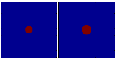
The code used to generate the figure is:
seg = imdilate(seg,strel_bol(3));
figure,volplot(seg);
An example of the imfill function is given below. This is the case, for example, in which we want to fill the volume so that it constitutes a single entity. It results in being useful for triangulation, as explained in one of the techniques to obtain the outer-most surface (i.e. the skin).
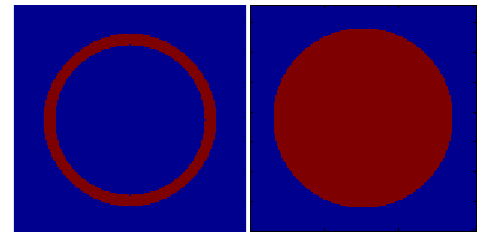
The code used to generate the figure is:
seg = imfill(seg,'holes');
figure,volplot(seg);
The same effect can be reached with the use of another morphology function: bwlabeln. This function classifies the cluster of neighboring voxels and attaches a label to them, so that different objects can be easily distinguished (and processed) in the successive steps.
A list of the headmodel functions
- ft_headmodel_asa
- ft_headmodel_dipoli
- ft_headmodel_openmeeg
- ft_headmodel_bemcp
- ft_headmodel_concentricspheres
- ft_headmodel_fns
- ft_headmodel_simbio
- ft_headmodel_halfspace
- ft_headmodel_infinite
- ft_headmodel_localspheres
- ft_headmodel_singleshell
- ft_headmodel_singlesphere
- ft_headmodel_strip
The functions in Forward module
This functions are responsible to generate the lead fields for the different available methods. They are contained in the Forward/private folder.
- eeg_halfspace_medium_leadfield.m
- leadfield_simbio.m
- eeg_leadfield1.m
- eeg_leadfield4.m
- meg_leadfield1.mexXXX
- eeg_leadfield4_prepare.m
- eeg_leadfieldb.m
- halfspace_medium_leadfield.m
- inf_medium_leadfield.m
- leadfield_fns.m
- eeg_strip_monopole.m
- inf_medium_leadfield.m
- meg_forward.m
- meg_ini.m
Functions that maybe should not be here
- ama2vol.m
- fitsphere.m
- headcoordinates.m
- transfer_elec.m
Examples of volumetric functions are:
ana2ana functions:
- ft_read_mri
- ft_volumereslice
- ft_volumerealign
- ft_volumenormalise
- ft_volumesmooth
ana2seg functions:
- ft_volumesegment
- ft_volumethreshold
Morphology operators
seg2seg functions:
- e.g., the functions from the image processing toolbox
seg2mesh functions:
- ft_prepare_mesh
- ft_surface_extract](#Triangulation methods)**
mesh2mesh functions:
- ft_read_headshape
- ft_read_sens
- ft_electroderealign
- ft_prepare_mesh
- ft_surfaceextract
- ft_surfacerefine
- ft_surfacedownsample
- ft_surfacesmooth
- ft_surfacecheck, like closed? outward pointing? etc
mesh2vol functions:
- ft_prepare_headmodel
The ft_check_surface function
This function performs a set of sanity checks on the triangulated surfaces which allow to generate quantitative indexes.
We want to check
- the area of the entire surface
- the intersection of two surfaces
- the orientation of the triangles (outwards/inwards)
- the presence of disconnected triangles
- the presence of redundant vertices
- the surface represents a closed area (i.e. the brain)
The reason for this function to exist is to understand if the mesh represents a regular and correct triangulation (e.g., the area is in cm2 and not km2). These checks are required in order to generate a correct forward model and are model dependent. Some of the steps might require direct interaction with the operator for a further visual inspection.
The implementation of the volume and mesh routines
The routines that handle voxel based volumes can be described as functions that go from an anatomical input to segmented binary images (ana2seg routines), from anatomy to processed anatomy (ana2ana routines) and from segmented volumes into segmented volumes (seg2seg routines). The characteristic of voxel based routines is that the volumes are regular (cubic voxels upon reslicing).
Alternatively the routines that deal with geometric information other that voxel-based are handling the following geometrical object
- 0d : a point
- 1d : a line
- 2d : a plane/triangle/surface
- 3d : tetrahedra or hexahedra (irregular volume information, non voxel based)
(they might belong to the mesh2mesh routines class)
All routines that create head models must allow the transition from all objects to all others (if possible), and from voxel based images to geometrical objects. For example the routine prepare_mesh_manual segments boundaries directly from the MRI scans and generates connected lines (if goes from ana to 1d objects).