Why does my EEG headmodel look funny?
If you create an EEG (or MEG) headmodel from an anatomical MRI image, it may happen that the one-shoe-fits-almost-all recipe that you are following does not work that well. For instance, using the pipeline sketched in the EEG BEM headmodel tutorial, it could be that the meshes you end up with contain artifacts. For instance, there may be undesired ‘horns’ attached to the head or brain surface, or there might be holes. The below code shows two situations that might happen. Sometimes, things can be relatively easily solved, by tweaking judiciously the tweakable parameters in the pipeline used, but sometimes there’s no way around going in by hand and to manually adjust/fix the faulty segmented images. This FAQ only sketches 2 situations that can be solved relatively easily. The first example, uses the single subject template MRI from FieldTrip, which has quite a prominent aliasing artifact at the top of the image. Using a segmentation approach with the default settings will result in a ‘strange’ head surface. This can be alleviated with tweaking some segmentation parameters. The second example introduces an manipulated MRI image, that has an inhomogeneous intensity. This might occur for instance if the participant was wearing an EEG cap with electrodes while the image was acquired. Satisfactory results can be obtained if the intensity bias in the image is corrected prior to segmenting. For this, one can use the function ft_volumebiascorrect.
% load an anatomical mri
[ftver, ftpath] = ft_version;
mri = ft_read_mri(fullfile(ftpath, 'template/anatomy', 'single_subj_T1_1mm.nii'));
mri.coordsys = 'acpc';
The image on disk has an ugly aliasing artifact at the top, causing the standard settings to create an ugly segmentation. increasing the threshold for the scalp segmentation, and switching off the smoothing is sufficient to fix it in this case. But let’s first show that it leads to a segmentation problem, and a funky scalp surface.
cfg          = [];
cfg.output   = {'brain','skull','scalp'};
segmentedmri0 = ft_volumesegment(cfg, mri);

cfg             = [];
cfg.tissue      = {'brain','skull','scalp'};
cfg.numvertices = [3000 2000 1000];
bnd0            = ft_prepare_mesh(cfg, segmentedmri0);

figure;
ft_plot_mesh(bnd0(3), 'facecolor',[0.4 0.4 0.4]);
view([0 0]);
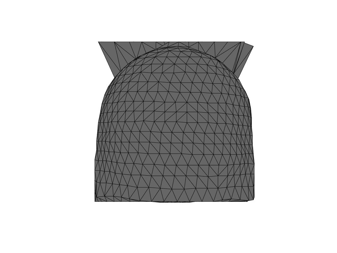
Figure 1. Aliasing artifact at the top leads to horns
Adjusting the settings for the segmentation is helpful in this case, but will not always work.
cfg          = [];
cfg.output   = {'brain','skull','scalp'};
cfg.scalpthreshold = 0.2;
cfg.scalpsmooth  = 'no';
segmentedmri = ft_volumesegment(cfg, mri);

cfg             = [];
cfg.tissue      = {'brain','skull','scalp'};
cfg.numvertices = [3000 2000 1000];
bnd             = ft_prepare_mesh(cfg, segmentedmri);

figure;
ft_plot_mesh(bnd(3), 'facecolor',[0.4 0.4 0.4]);
view([0 0]);

Figure 2. Adjustment of segmentation parameters gets rid of the aliasing artifact
Another, relatively easy to address, issue might result from image inhomogeneities. We have observed consequences of suboptimal segmentations in case subjects were wearing an EEG cap in the MRI scanner. Below, we first create an inhomogeneous image, and demonstrate the effect of this on the quality of the headmodel that is created from the segmented image. Then, we show that the problem is fixed if the bias in the image is corrected prior to running the segmentation.
First, we create a mask for the relevant anatomical data, so that the aliasing artifact can be zero’ed out, so that we don’t need to account for that anymore.
scalpmask = double(segmentedmri.scalp);

% fill the bottom
scalpmask(50:130,50:130,1) = 1;
pw_dir = pwd;
cd(fullfile(ftpath, 'private'));
scalpmask = volumefillholes(scalpmask);
cd(pw_dir);

mri2 = mri;
mri2.anatomy(~scalpmask) = 0; % avoid the strange aliasing effect

% change the homogeneity of the image
krn  = gausswin(181,2)*gausswin(201,2)';
K    = repmat(krn, [1 1 180]);
for k = 1:180
  K(:,:,k) = K(:,:,k).*(k./150);
end
blob = ones(mri2.dim);
blob(91+[-90:90], 101+[-100:100], 2:end) = max(1-K,0);

mri2.anatomy = mri2.anatomy.*blob;
ft_sourceplot([], mri2);
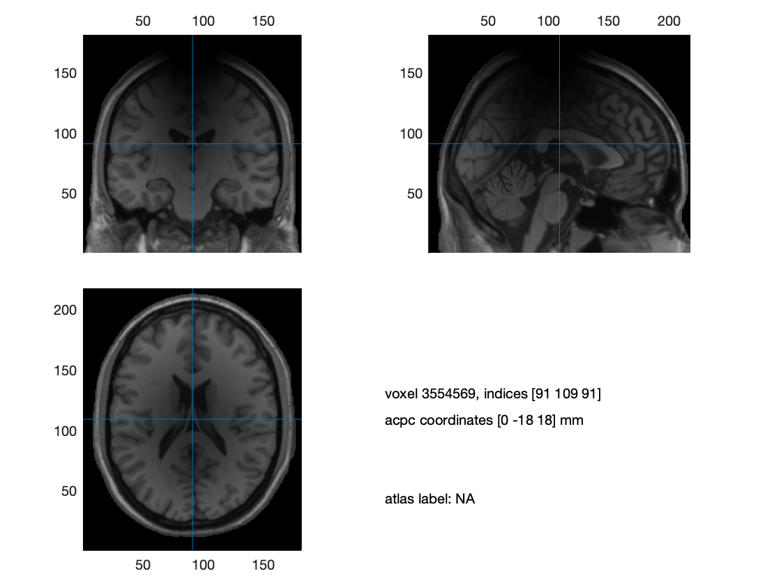
Figure 3. Inhomogeneous anatomical image
cfg          = [];
cfg.output   = {'brain','skull','scalp'};
segmentedmri2 = ft_volumesegment(cfg, mri2);

cfg             = [];
cfg.tissue      = {'brain','skull','scalp'};
cfg.numvertices = [3000 2000 1000];
bnd2            = ft_prepare_mesh(cfg, segmentedmri2);
The above already throws a warning that the segmentation is not star-shaped, which is an indication that something fishy might be going on. This is corroborated by the figure that is generated below:
figure;
ft_plot_mesh(bnd2(3), 'facecolor',[0.4 0.4 0.4]);
view([90 0]);
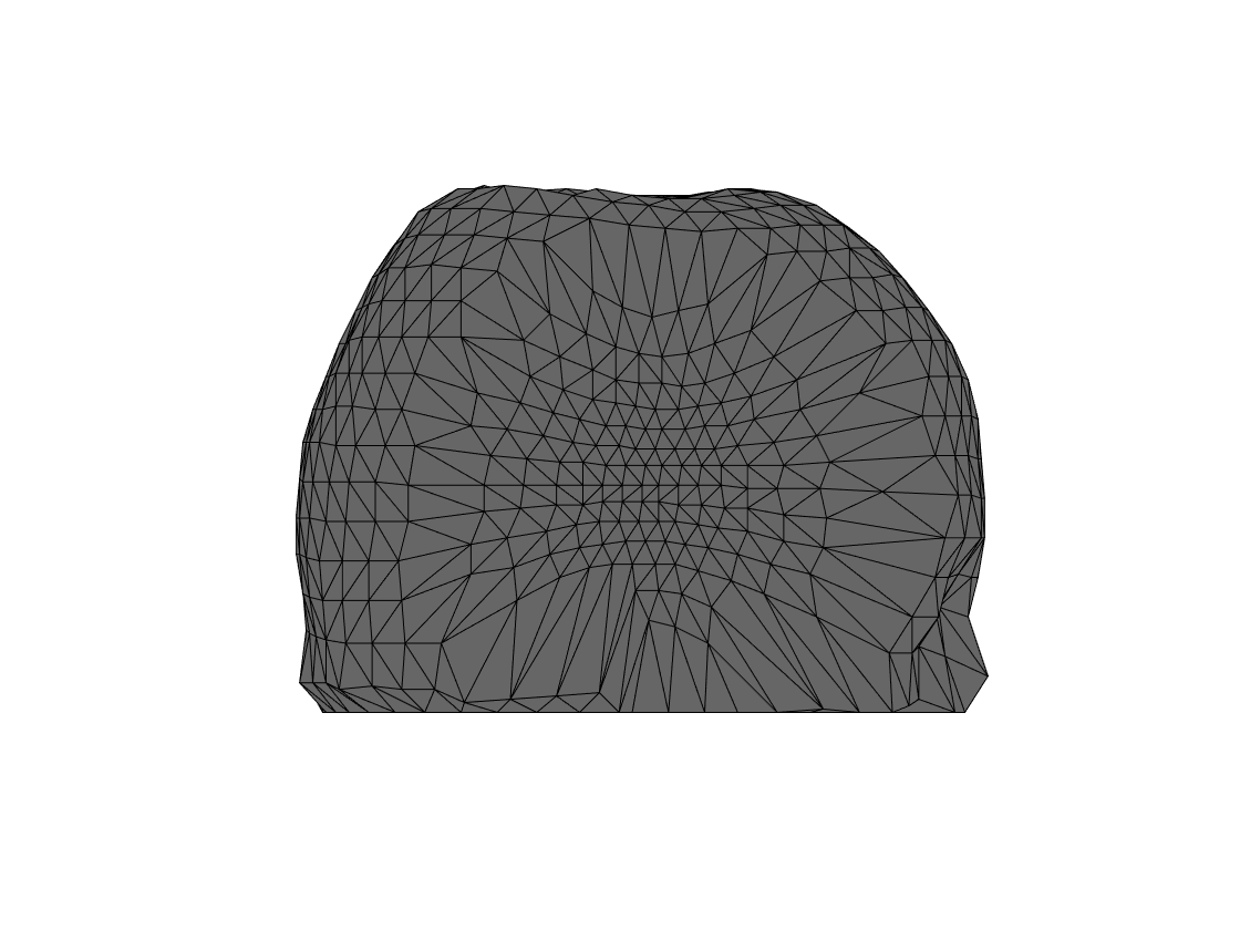
Figure 4. Failed headmodel
As mentioned above, the bias in the image can be corrected as follows:
% estimate the inhomogeneity and remove this bias
mri3 = ft_volumebiascorrect([], mri2);

cfg          = [];
cfg.output   = {'brain','skull','scalp'};
segmentedmri3 = ft_volumesegment(cfg, mri3);

cfg             = [];
cfg.tissue      = {'brain','skull','scalp'};
cfg.numvertices = [3000 2000 1000];
bnd3            = ft_prepare_mesh(cfg, segmentedmri3);

figure;
ft_plot_mesh(bnd3(3), 'facecolor',[0.4 0.4 0.4]);
view([90 0]);
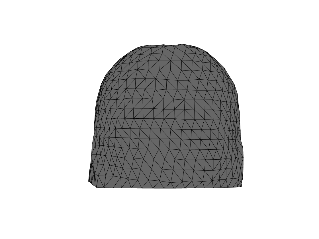
Figure 4. Headmodel after inhomogeneity correction