documentation / example / other / opm_sensors /
Designing 3D printed helmets for different OPM sensor types
This example shows how to design a 3D printed helmet with different OPM sensor types. The initial part deals with reading the helmet design and distributing the sensors. This is the same as the tutorial for designing a custom 3D printed OPM helmet. The second part shows how to distribute the sensor holders (and holes) over the helmet.
Helmet and sensor distribution
For demonstration purposes we start with a very simple spherical helmet that is 10 mm thick, and a small number of OPM sensor locations.
headshape = ft_read_headshape('spherical-head.stl');
helmet = ft_read_headshape('spherical-helmet.stl');

% the CTF coordinate system has X towards the nose and Y towards the left
headshape.coordsys = 'ctf';
helmet.coordsys = 'ctf';

nas = [+100 0 0];
ini = [-100 0 0];
lpa = [0 +100 0];
rpa = [0 -100 0];

headshape.fid.pos = [
    nas
    ini
    lpa
    rpa
];

headshape.fid.label = {
    'nas'
    'ini'
    'lpa'
    'rpa'
};

% this places a lot of electrodes, see https://doi.org/10.1016/s1388-2457(00)00527-7
cfg = [];
cfg.fiducial.nas = nas;
cfg.fiducial.ini = ini;
cfg.fiducial.lpa = lpa;
cfg.fiducial.rpa = rpa;
cfg.method = '1020';
cfg.feedback = 'yes';
elec = ft_electrodeplacement(cfg, headshape);

% we select a small number of locations to distribute the OPM sensors
chansel = ft_channelselection({'eeg1020', '-Fpz', '-Oz'}, elec.label);
FieldLine sensors
For the first version of the Donders baby OPM system we have designed the following FieldLine sensor holders.
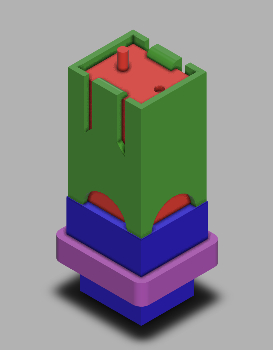
Note that this rendered image does not show all details, as it plots the sensor, the sensor holder, the hole and the padding on top of each other. The Fusion360 online 3D rendering (see link below) allows exploring the different elements.
The design can be visualised on and downloaded from https://a360.co/4m1oIPg. The STL files used in this example are available from our download server.
% distribute the OPM sensor elements according to the pre-determined locations
cfg = [];
cfg.elec = elec;
cfg.channel = chansel;
cfg.outwardshift = 10/2; % the helmet is 10 mm thick, the bottom of the sensor holder will be halfway in
cfg.template = 'fieldline_sensor.stl';
[tmpcfg, sensor] = ft_sensorplacement(cfg, headshape);
cfg.template = 'fieldline_holder.stl';
[tmpcfg, holder] = ft_sensorplacement(cfg, headshape);
cfg.template = 'fieldline_hole.stl';
[tmpcfg, hole] = ft_sensorplacement(cfg, headshape);
cfg.template = 'fieldline_padding.stl';
[tmpcfg, hole] = ft_sensorplacement(cfg, headshape);
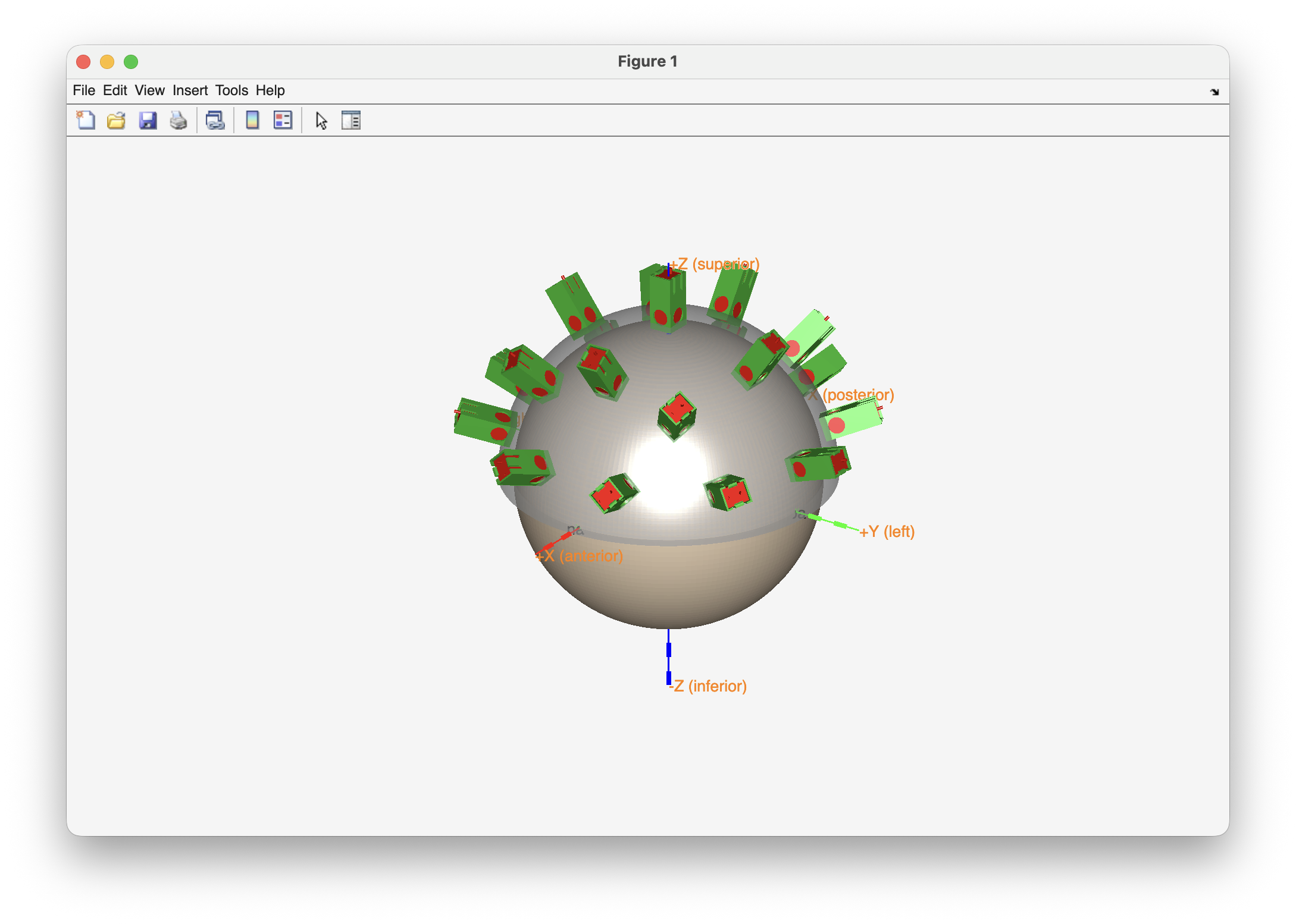
% make a 3D figure that shows all elements together
figure
ft_plot_headshape(headshape, 'facecolor', 'skin', 'facealpha', 1, 'axes', true);
ft_plot_mesh(helmet, 'facecolor', 'lightgray', 'facealpha', 0.5, 'edgecolor', 'none');
ft_plot_mesh(sensor, 'facecolor', 'red', 'facealpha', 1, 'edgecolor', 'none');
ft_plot_mesh(holder, 'facecolor', 'limegreen', 'facealpha', 1, 'edgecolor', 'none');
% ft_plot_mesh(hole, 'facecolor', 'b', 'facealpha', 0.5, 'edgecolor', 'none');
% ft_plot_mesh(padding, 'facecolor', 'm', 'facealpha', 0.5, 'edgecolor', 'none');
view(125, 25)
ft_headlight
Mag4Health sensors
For the Mag4Health sensors we have adapted the design from Mag4Health to give them a flat and square base to facilitate glueing them into the holes in the helmet. The OPM sensors can slide in the holder, and the ring is used to fixate the sensor at a certain depth.
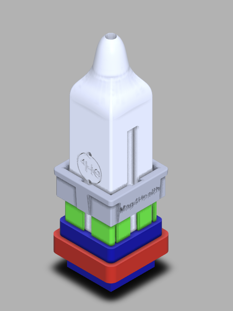
Note that this rendered image does not show all details, as it plots the sensor, the sensor holder, the ring, the hole and the padding on top of each other. The Fusion360 online 3D rendering (see link below) allows exploring the different elements.
The design can be visualised on and downloaded from https://a360.co/4s48B4G. The STL files used in this example are available from our download server.
% distribute the OPM sensor elements according to the pre-determined locations
cfg = [];
cfg.elec = elec;
cfg.channel = chansel;
cfg.outwardshift = 10/2; % the helmet is 10 mm thick, the bottom of the sensor holder will be halfway in
cfg.template = 'mag4health_sensor.stl';
[tmpcfg, sensor] = ft_sensorplacement(cfg, headshape);
cfg.template = 'mag4health_holder.stl';
[tmpcfg, holder] = ft_sensorplacement(cfg, headshape);
cfg.template = 'mag4health_ring.stl';
[tmpcfg, ring] = ft_sensorplacement(cfg, headshape);
cfg.template = 'mag4health_hole.stl';
[tmpcfg, hole] = ft_sensorplacement(cfg, headshape);
cfg.template = 'mag4health_padding.stl';
[tmpcfg, hole] = ft_sensorplacement(cfg, headshape);
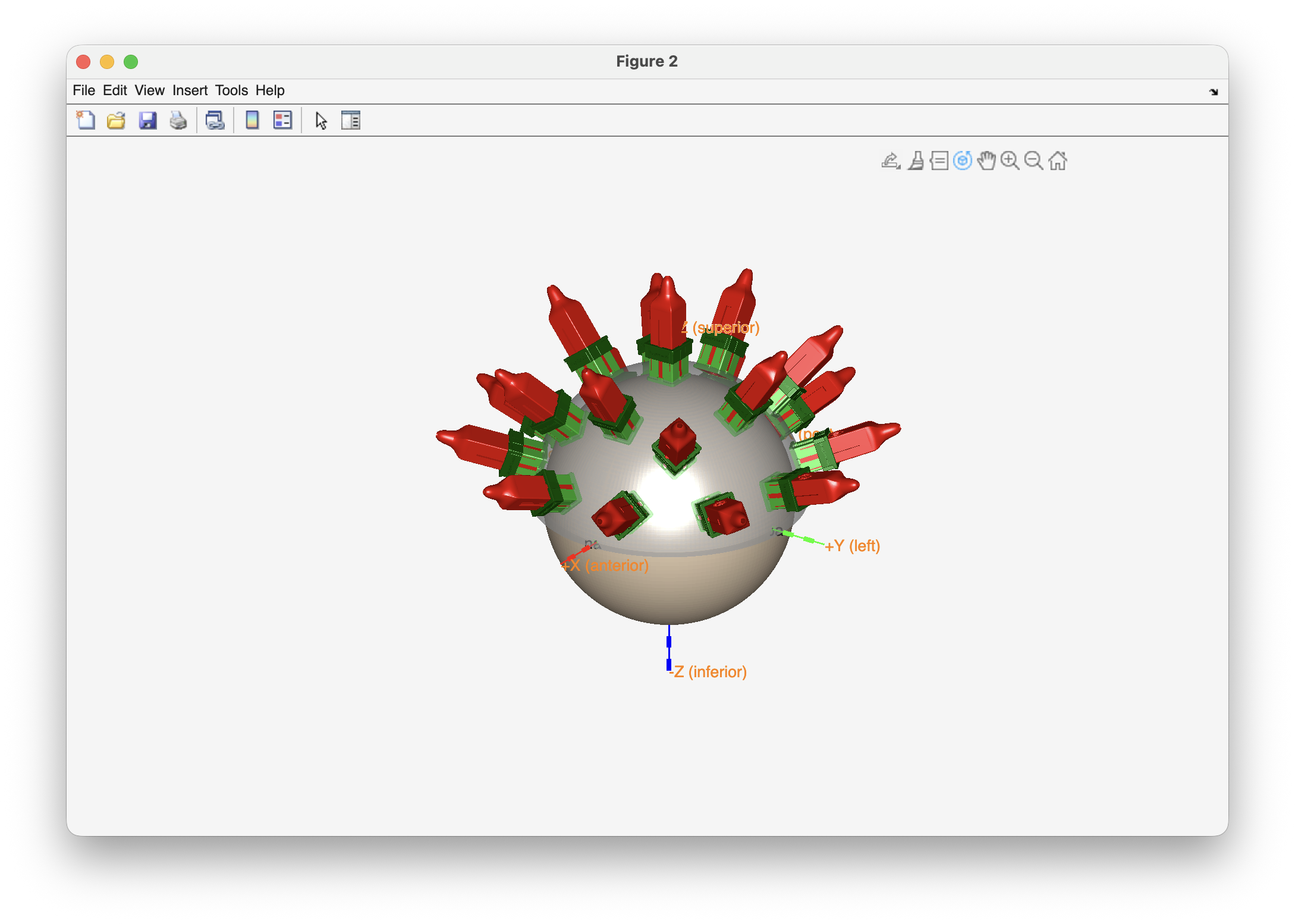
% make a 3D figure that shows all elements together
figure
ft_plot_headshape(headshape, 'facecolor', 'skin', 'facealpha', 1, 'axes', true);
ft_plot_mesh(helmet, 'facecolor', 'lightgray', 'facealpha', 0.5, 'edgecolor', 'none');
ft_plot_mesh(sensor, 'facecolor', 'red', 'facealpha', 1, 'edgecolor', 'none');
ft_plot_mesh(holder, 'facecolor', 'limegreen', 'facealpha', 1, 'edgecolor', 'none');
ft_plot_mesh(ring, 'facecolor', 'darkgreen', 'facealpha', 1, 'edgecolor', 'none');
% ft_plot_mesh(hole, 'facecolor', 'y', 'facealpha', 0.5, 'edgecolor', 'none');
% ft_plot_mesh(padding, 'facecolor', 'm', 'facealpha', 0.5, 'edgecolor', 'none');
view(125, 25)
ft_headlight
QuSpin and Cerca sensors
We don’t have a design for the QuSpin and Cerca Magnetics sensors yet. You could take the FieldLine or the Mag4Health design above and rescale it to fit the sensors, or you could start with an OPM sensor holder design from scratch.
If you do make a design, please consider sharing it with other researchers. You can contact us to have it added here.